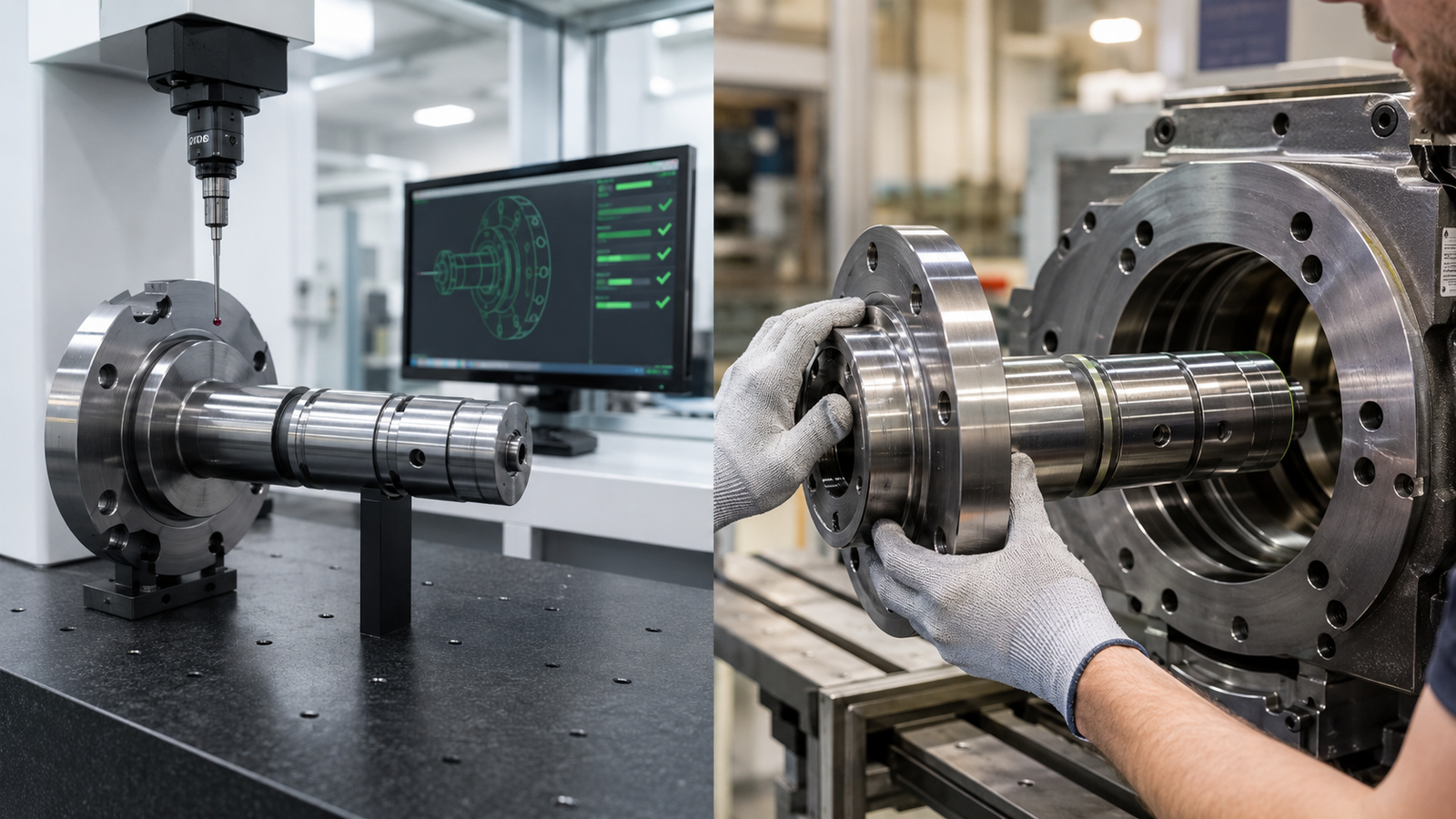





Long shaft machining and inspection involves more than producing a component to the specified length. It requires a coordinated manufacturing and measurement plan that addresses dimensions, geometric features and drawing acceptance criteria.
For buyers managing custom components with several operations, coordinating machining, bending and inspection can reduce supplier handoffs. EXCEL Components starts with your drawing and functional requirements to discuss an appropriate manufacturing and delivery approach.
Define Long Shaft Machining and Inspection Requirements
Quality planning begins before the first cut. Material, length, diameter, mating features and operating conditions help establish which characteristics need particular attention during manufacturing and inspection.
A clear drawing gives purchasing, production and quality teams a shared reference. Identifying the latest revision and highlighting critical features helps prevent different departments or suppliers from working to different assumptions.
Separate Size from Geometry
Diameter and length are dimensional characteristics, while straightness and coaxiality describe geometric characteristics. Meeting a diameter tolerance does not demonstrate that every geometric requirement has been satisfied.
Where a requirement is unclear, clarification should take place before production. A general request for high precision provides less guidance than a drawing with defined tolerances and measurement references.
Control Shaft Deformation
Long, slender workpieces require consideration of support, cutting conditions and the risk of deflection or vibration. The approach should reflect the component’s proportions, material and features rather than rely on the same setup for every part.
Turning, milling and secondary operations also need a suitable sequence. Clamping locations and intermediate stages can influence how critical surfaces are produced and subsequently inspected.
Review Tolerances by Feature
In long shaft machining and inspection, achievable tolerances must be assessed against the actual geometry and process conditions. A tolerance achieved on one feature should not automatically be applied to every length, material or component.

Plan Bend Radius and Angle
Tubes and other components requiring bending need specified radii, angles, locations and reference points. Material properties, springback and local shape changes should be considered during process evaluation.
The operation sequence should account for how bending may affect previously machined features. The review can identify characteristics that require checking after forming or additional processing.
Long shafts and bent tubes may represent separate products rather than consecutive stages of the same component. One-stop service means coordinating the operations each design requires, with the scope agreed for the individual project.
Measure the Features That Matter
Inspection planning starts by identifying the characteristic that must be verified. Instrument selection then depends on accessibility, workpiece positioning, measurement range and acceptance criteria.
Optical projection and contact contour measurement serve different inspection needs. Neither method should be selected solely because it is available without checking whether it can evaluate the specified feature.
Check Accessible Profile Features
A contact contour instrument can assess local radii, angles and transitions where stylus access, travel and tracing-angle limits permit. The workpiece must be positioned so the measured profile corresponds to the intended feature.
Mitutoyo’s technical guide to contour measurement explains profile analysis and stylus tracing limitations. This manufacturer reference helps explain why measurement methods must be matched to feature geometry.

Distinguish Profiles from 3D Geometry
A local contour trace does not verify a component’s complete three-dimensional geometry. Overall shape and relationships between spatial features may require complementary inspection methods.
Verify Drawing Requirements
Measurement results should correspond to the drawing’s nominal values, tolerances and references. Agreeing on inspection items, sampling arrangements and reporting formats before production helps establish clear expectations.
Reports are most useful when measured characteristics can be identified clearly. Their scope should reflect the project agreement rather than assume every component requires an identical inspection package.
| Review Area | Information to Confirm |
|---|---|
| Material and dimensions | Material specification, length, diameter and drawing revision |
| Geometric requirements | Specified geometric tolerances and datum references |
| Bending, where applicable | Bend radii, angles, locations and positioning references |
| Delivery and inspection | Quantities, delivery dates, surface treatments and reporting requirements |
Coordinate Through One Contact
A coordinated service brings machining, bending and inspection requirements into one project discussion. It reduces repeated explanations and helps keep process decisions aligned with finished-part requirements.
When a drawing or process changes, the same acceptance criteria should guide the review. This provides a clearer basis for discussing feasibility, inspection scope and delivery expectations.
Share Your Drawing for Review
Prepare the following information to help our team understand your project. Include any assembly conditions or inspection requirements that are not fully described on the drawing.
- Current drawings and material specifications.
- Quantities and target delivery dates.
- Critical tolerances and bending requirements.
- Surface treatments and inspection documentation needs.
Looking for long shaft machining and inspection support? Send EXCEL Components your requirements to discuss a coordinated manufacturing and inspection approach suited to your component.