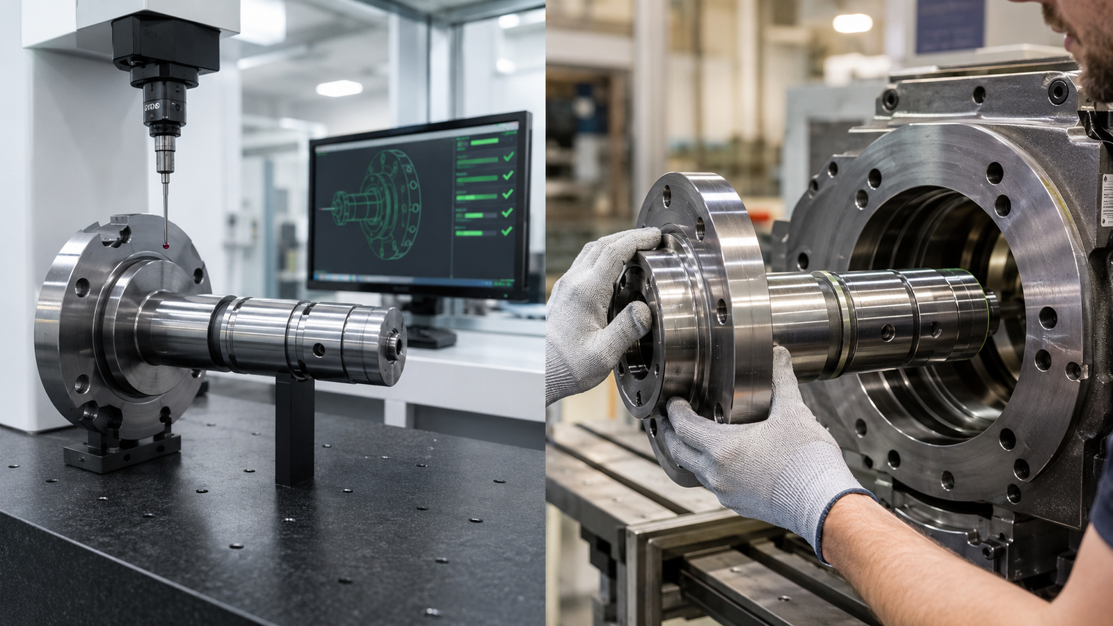





A groove that is a few microns too shallow, a radius slightly out of tolerance or a sealing surface that is rougher than specified can pass a visual check. It can still cause leaks, wear or assembly problems. A profilometer verifies these details with a stylus that touches the part and records its true surface profile.
When your machining supplier has a profilometer in its own quality lab, you get numerical results, faster feedback and fewer surprises at incoming inspection. This guide explains the four inspection advantages of a contact profilometer, how it compares with a profile projector and what to send for profile-critical parts.
Key points for buyers
- A contact profilometer records the part profile with micron-level accuracy.
- It measures surface roughness as well as curves, grooves, radii and threads.
- Digital measurement is more objective than reading a magnified silhouette on a profile projector.
- An in-house profilometer lets the supplier correct the process at first-article inspection, not after shipment.
A Profilometer Turns Hidden Surface Details into Measurable Data
A profilometer records the profile of a surface along a defined path. In a contact profilometer, a stylus with a known tip geometry moves across the workpiece. The instrument records the stylus displacement, and software evaluates the traced profile against the drawing.
Depending on the configuration and stylus, a profilometer can evaluate:
- Surface texture: roughness parameters such as Ra and Rz, and minute surface variations
- Radii and angles: fillets, corner radii, chamfers and tapers
- Grooves and steps: groove width, depth and bottom radius, and step heights
- Threads and curves: thread profile elements and curved contours
- Profile comparison: deviation of the traced profile from a nominal CAD contour
Some systems use separate detectors or styli for contour and roughness measurement because the two tasks need different resolution and measuring ranges. Contour measurement covers a larger vertical range to capture radii, steps and angles, while roughness measurement uses a finer stylus tip to resolve microscopic peaks and valleys. A supplier should confirm which configuration is used for each characteristic on your drawing.

4 Profilometer Inspection Advantages That Prevent Hidden Part Defects
1. Precise Surface Micro-Topography Measurement
A profilometer accurately detects surface roughness and minute variations that cannot be judged by eye or by touch. This matters wherever surface finish affects function: sealing surfaces, bearing seats, sliding parts and surfaces that will be plated or coated.
Instead of comparing a part with a roughness sample, the instrument reports values such as Ra and Rz against the drawing requirement. Buyers receive a clear pass or fail decision based on data.
2. Micron-Level Accuracy
A profile projector enlarges the part’s silhouette, and the operator reads edges against a screen or overlay chart. The result depends on magnification, edge sharpness and the operator’s judgment.
A profilometer measures the profile digitally at micron level. Software fits lines, arcs and points to the trace and calculates the dimension, so a radius is reported as a value such as R0.48 against R0.5 ±0.05, not as “looks acceptable.” Results are more repeatable between operators and between measurements.
Digital results also make trend analysis possible. Measured values from successive parts can be plotted to show whether a feature is drifting toward a tolerance limit, which supports statistical process control for critical characteristics.
3. Complex Geometry Inspection
Many functional features are small, curved or partly hidden: shaft shoulder radii, O-ring and snap-ring grooves, thread profiles and blended transitions. These are difficult to check with calipers, micrometers or radius gauges.
A profilometer is suitable for curves, grooves, radii and threads. One trace can capture several related features, such as a groove’s width, depth and corner radii, so their relationships are checked together.

4. Contact-Type Measurement
The probe directly contacts the workpiece surface. The measurement is therefore not influenced by reflective machined surfaces, edge shadows or the color of the material, which can affect optical methods. This gives more precise and reliable data on the actual surface.
Contact measurement also reaches features that do not appear in a silhouette, such as internal grooves and profiles on faces, where the stylus can access them.
An In-House Profilometer Catches Problems Before Parts Ship
Owning the instrument is only part of the value. Having it in the same facility as the CNC lathes and machining centers changes how quality is managed:
- Faster first-article approval: the first part is measured shortly after machining, and offsets are corrected before the batch continues.
- Process monitoring: periodic checks during a run show tool wear trends before parts go out of tolerance.
- Better feedback to machining: the trace shows how a profile deviates, which helps engineers correct tool geometry or programs instead of sorting parts.
- Traceable reports: results can be linked to drawing revision, lot number and date, supporting FAI, PPAP and audits under IATF 16949.
- Fewer handoffs: one team is responsible for both making the feature and proving that it meets the drawing.
How Profilometer Inspection Works from Drawing Review to Report
Reliable results depend on planning as much as on the instrument. A typical profilometer inspection follows five steps.
1. Identify the Characteristics to Verify
The QA team reviews the drawing and marks the radii, angles, grooves, threads and surface roughness requirements that need measurement. Unclear callouts, such as a roughness value without a location, are clarified with the customer before production starts.
2. Fixture and Align the Part
The part is positioned so that the stylus travels along the intended section, for example through the axis of a shaft or perpendicular to the machining lay. Poor alignment can make a correct radius appear out of tolerance, so setup is checked before every critical measurement.
3. Select the Stylus and Measurement Conditions
Stylus tip, measuring force, traverse length and speed are chosen to suit the feature and the material. Roughness measurement also requires appropriate cutoff and evaluation length settings so that results are comparable with the customer’s own inspection.
4. Trace and Evaluate the Profile
The stylus traces the section, and software fits lines and arcs to the recorded profile. Measured values are compared with the nominal dimensions and tolerances on the drawing, and each characteristic receives a clear pass or fail status.
5. Report and Feed Back to Production
Results are documented in the agreed report format. If a value is near or outside the limit, the machining team adjusts tool offsets, tool geometry or cutting conditions, and the part is measured again before production continues.
Profilometer vs. Profile Projector: Measured Data Instead of Visual Judgment
| Method | Best For | Limitations |
|---|---|---|
| Contact profilometer | Surface roughness, radii, angles, grooves, threads and profile comparison with micron-level accuracy | Measures one section per trace. Stylus tip size and tracing angle limit what it can reach. |
| Profile projector | Fast silhouette checks of outer profiles at magnification | Relies on optical magnification and operator reading. Limited for internal features and surface texture. |
| Coordinate measuring machine (CMM) | 3D positions, geometric tolerances and datum relationships | Small radii, fine profile details and roughness need other methods. |
| Hand tools and gauges | Diameters, lengths and go/no-go checks | Cannot give numerical values for most profile or surface features. |
The right method depends on the characteristic to be verified, and many parts need more than one. For an example of matching methods to features, see our guide to long shaft machining and inspection.
Clear Surface Roughness Callouts Prevent Inspection Disputes
A roughness value on its own does not always tell the supplier how to measure it. Two laboratories can report different results for the same surface if the measurement conditions are not defined. Buyers can avoid disputes by specifying the following points on the drawing or inspection plan:
- Parameter: Ra (arithmetic mean deviation) is the most common, but Rz (maximum height of the profile) is more sensitive to isolated peaks and scratches. Specify the parameter that the function depends on.
- Location: mark the exact surfaces where the requirement applies, such as a bearing seat or seal face, instead of applying one value to the whole part.
- Direction: roughness is usually measured perpendicular to the machining lay. State it clearly if another direction is required.
- Cutoff and evaluation length: standard values apply unless stated. If your quality system requires specific settings, include them in the requirements.
- Standard: reference the applicable standard, such as ISO 21920 (which replaces ISO 4287 and ISO 4288) or ASME B46.1.
Agreeing on these points before production means the inspection report answers the question the drawing actually asks, and incoming inspection can repeat the measurement under the same conditions.
Profilometer Limits Show When Other Inspection Methods Are Needed
- Stylus access: very narrow or deep internal features may not be reachable.
- Stylus tip radius: features smaller than the tip geometry cannot be fully resolved, so very sharp corners appear rounded.
- Tracing angle: very steep flanks may need a different setup or method.
- One section per trace: a trace does not verify the complete 3D geometry of the part.
- Contact force: on very soft or delicate surfaces, the measuring force and stylus selection must be considered.
Knowing these limits is part of good inspection planning. When a feature cannot be measured reliably with a profilometer, the QA team can use a CMM, a profile projector, a sectioned sample or a surface replica instead, and the method is agreed with the customer before production.
Profilometer Reports Give Buyers Evidence They Can Audit
An inspection report is only useful if a buyer can understand what was measured and how. A clear profilometer report typically includes:
- Part number, drawing revision, lot number and measurement date
- The measured section or surface, identified on a sketch or drawing excerpt
- The traced profile graph with fitted elements such as arcs and lines
- Nominal value, tolerance and measured value for each characteristic, with pass or fail status
- Roughness parameters with the cutoff and evaluation length used
- Instrument identification and calibration status
These details make it possible to compare results between the supplier and the customer’s incoming inspection. When results differ, both sides can check whether the same section, setup and conditions were used, which resolves most disagreements quickly and without re-shipping parts.
For customers working under IATF 16949, profilometer reports can also support first-article and PPAP submissions as evidence of dimensional and surface conformance.
Parts That Benefit Most from Profilometer Inspection
Profilometer inspection adds the most value where a small profile or surface deviation has a large functional effect:
- Automotive shafts and pins: shoulder fillets, undercuts and bearing seats affect fatigue life and assembly fit.
- Hydraulic and pneumatic fittings: O-ring grooves and sealing faces must meet both dimensional and roughness requirements to prevent leaks.
- Industrial fasteners and threaded parts: thread flank angles, root radii and under-head fillets influence load capacity and assembly.
- Automation and robotics components: sliding and rotating surfaces need controlled roughness for smooth, repeatable motion.
- Bent tubes and fluid lines: bend radii, formed tube ends and O-ring grooves on fittings must match the drawing so that lines route correctly and seal reliably.
- Cold-forged and turned components: form-tool profiles and forged transitions can be checked at first article and monitored as tools wear.
If your part has any of these features, mark them on the drawing as critical. This lets the supplier plan inspection frequency, sampling and reporting from the start instead of adding checks after a problem appears.

A Passing Visual Check Can Still Hide an Out-of-Tolerance Radius
Consider a typical stepped shaft. The drawing specifies a small shoulder fillet where a bearing seats and a maximum roughness value for the bearing seat. Under a magnifier the shoulder looks clean, and a radius gauge appears to fit. By visual standards, the part passes.
A profilometer trace can tell a different story. The fillet may be slightly larger than the tolerance allows because of the tool nose radius, which can stop the bearing from seating fully against the shoulder. The seat may also be rougher than specified if finishing conditions have drifted. Neither problem is easy to see, but both can lead to noise, wear or premature failure in service.
When this is found at first-article inspection, the fix is straightforward: the machining team adjusts the tool or finishing conditions, the part is measured again, and production continues with confidence. When it is found at the customer’s assembly line, the cost includes sorting, rework, delays and lost trust. This is the practical value of measuring profile features with data instead of judging them by eye.
Mitutoyo Profilometer Capability for Precision Metal Parts
| Item | Specification |
|---|---|
| Instrument | Mitutoyo Formtracer Avant profilometer |
| Measurement type | Contact stylus measurement |
| Surface texture | Roughness parameters such as Ra and Rz |
| Geometry | Curves, grooves, radii, angles, step heights and threads |
| Accuracy | Micron-level measurement |
| Reports | Profile trace reports and first-article inspection reports |
| Quality system | IATF 16949:2016 |
Profilometer inspection is part of our custom metal parts machining and inspection service, from CNC turning and milling to bending and final verification.
Profilometer Inspection Questions Buyers Ask Before Ordering
What is a profilometer used for in metal machining?
It is used to measure surface roughness and the profile of machined features, such as radii, angles, grooves, step heights and threads, with micron-level accuracy.
What is the difference between a profilometer and a profile projector?
A profile projector shows a magnified silhouette that an operator reads optically. A contact profilometer traces the actual surface with a stylus and calculates the result digitally. It also measures surface roughness and features that do not appear in a silhouette.
Can a profilometer measure surface roughness?
Yes. With a suitable stylus and setup, a profilometer evaluates roughness parameters such as Ra and Rz as well as minute surface variations.
When should I use a CMM instead of a profilometer?
Use a CMM for 3D positions, geometric tolerances and relationships between features in different planes. Use a profilometer for surface texture and detailed profile features along a section. Many parts need both.
Can you include profilometer reports with each shipment?
Yes. The report scope, sampling frequency and format are agreed for each project before production, so the documentation matches your quality requirements.
How often should profile features be measured during production?
It depends on the risk of the feature and the stability of the process. Common approaches include first-article measurement, periodic checks at defined intervals or after tool changes, and final inspection samples. The frequency is agreed in the inspection plan before production.
Do you need a 3D model to perform profilometer inspection?
No. A dimensioned 2D drawing is enough for most profile and roughness checks. A 3D model or DXF contour is useful when the traced profile must be compared with a nominal shape.
Send Your Drawing for a Profilometer Inspection Review
Prepare the following information to help our team plan machining and inspection for profile-critical parts:
- Current drawing (PDF) and 3D model (STEP) with revision number.
- Material specification and any heat treatment or surface treatment.
- Surface roughness requirements and where they apply.
- Critical radii, angles, grooves and threads with their tolerances.
- Required report format, sampling frequency and documentation (FAI, PPAP, CoC).
- Quantities, annual volume and target delivery dates.
Need profilometer inspection for surface finish, radii, grooves or threads? Send EXCEL Components your drawing to discuss a machining and inspection approach suited to your component.
See how we machine and inspect precision metal parts on the EXCEL Components YouTube channel.