




How to Verify Drawing Tolerances: connect drawing requirements, appropriate measurement methods, and documented inspection results before accepting custom components. A supplier’s “PASS” statement alone does not explain the acceptance basis. Buyers need evidence showing which characteristics were checked and how conformity was assessed.
How to Verify Drawing Tolerances: Identify Dimensions That Affect Assembly
For non-standard fasteners, mating diameters, hole locations, and thread requirements can affect assembly. Before inspection, confirm the drawing revision, units, and applicable specifications, then agree on the characteristics requiring particular attention.
Start by asking which features control the fit between this component and the mating part. A diameter may be acceptable on its own while another requirement, such as hole position or a geometric relationship, remains unchecked. Identifying these relationships helps buyers define an inspection scope that reflects the intended function.
Convert the Tolerance into Checkable Dimensional Limits
A hypothetical diameter of 10.00 ±0.02 mm has dimensional limits of 9.98 to 10.02 mm. This example illustrates tolerance interpretation rather than EXCEL’s general manufacturing capability. Actual acceptance must follow the complete drawing and agreed decision rules.
Also confirm whether the drawing applies its requirements before or after a specified finishing operation. Coatings and other processing steps can affect the final dimensions of a component. The inspection stage should therefore match the condition in which the customer expects to receive and use the part.
How to Verify Drawing Tolerances with the Right Measurement Method
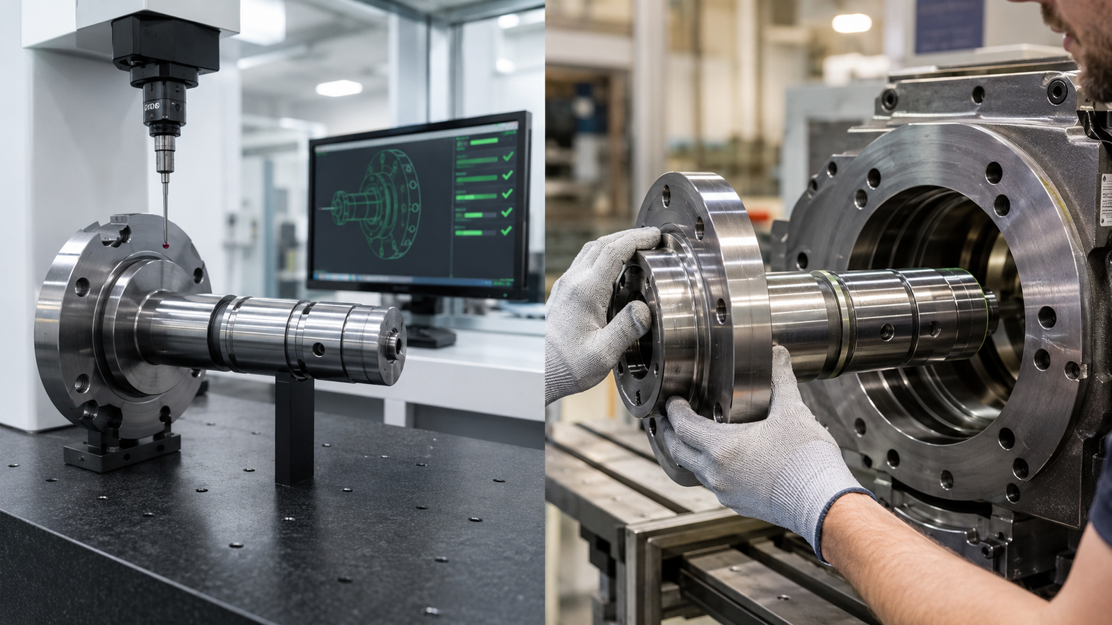
Owning a coordinate measuring machine (CMM) does not, by itself, establish reliable results for every characteristic. The measurement method must suit the feature and tolerance, with measurement locations, necessary datum setup, and equipment calibration status confirmed.

For a critical diameter, buyers should understand where readings are taken and whether multiple positions are needed. A single reading may not describe variation along the inspected surface. The appropriate procedure depends on the drawing requirements and the feature being evaluated, rather than a universal measurement routine.
Check Measurement Uncertainty and the Acceptance Rule
An instrument’s displayed decimal places do not establish measurement accuracy. NIST’s research on uncertainty and dimensional calibrations explains that measurement results are estimates. Results near specification limits should be assessed using the agreed conformity decision rule.
Calibration records are relevant, but they do not replace a suitable setup and measurement procedure. Where buyers and suppliers use different methods, discuss whether the results can be compared meaningfully. Resolving these questions before shipment can help avoid disagreement over apparently conflicting readings.
A PASS Statement Is Not Enough to Review Inspection Results
A useful dimensional inspection report should identify the part, drawing revision, and inspected batch. Each result should reference a drawing characteristic so buyers can compare specifications with measured values.

| Report Item | What Buyers Should Check |
|---|---|
| Drawing and characteristic identifiers | Confirm the correct revision and inspected feature. |
| Specifications and measured values | Check dimensional limits, units, and sample results. |
| Measurement and acceptance basis | Confirm the method and applicable acceptance rules. |
| Batch and sampling information | Identify the inspected batch and sample quantity. |
When reviewing the report, compare the drawing identifier, specification limits, and individual results together. Do not assume that a blank field means a characteristic was inspected and accepted. Ask the supplier to clarify missing information, the meaning of any symbols, and whether the report covers all requested characteristics.
An inspection report also has a defined scope. If it represents a sample from a batch, confirm how those samples were selected and identified. The report should not be interpreted as a record of complete inspection unless that inspection was actually performed and documented.
First-Article Acceptance Does Not Verify Every Production Part
First-article acceptance supports conformity for the inspected characteristics of the particular part examined, rather than every part in a batch. A single conforming dimension also cannot replace verification of related geometric requirements or assembly performance.
If a result does not meet the agreed requirements, establish how the affected parts will be identified and handled. Any proposed deviation should be reviewed through the customer’s approval process before shipment. A supplier should not substitute an informal judgment that the part is close enough.
Define Inspection Requirements Before Production
Agreeing on inspection scope before production helps reduce receiving disputes. Buyers should clarify the following requirements:
- Applicable drawing revision and critical dimensions.
- Measurement methods and conformity decision rules.
- Sample quantities, inspection frequency, and batch traceability needs.
- Inspection report content to be supplied.
How to Verify Drawing Tolerances Before Production
How to Verify Drawing Tolerances is a practical question to address before ordering custom components or non-standard fasteners. Share your drawing revision, critical dimensions, required quantities, and inspection requirements with EXCEL Components to discuss manufacturing feasibility and verification needs. Agreeing on the acceptance basis early helps keep requirements, measurement methods, and inspection evidence connected.