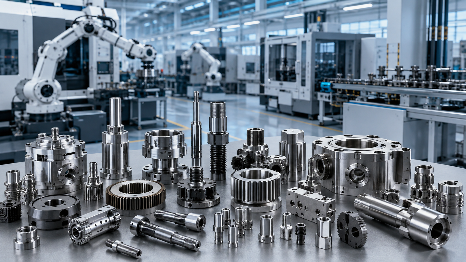






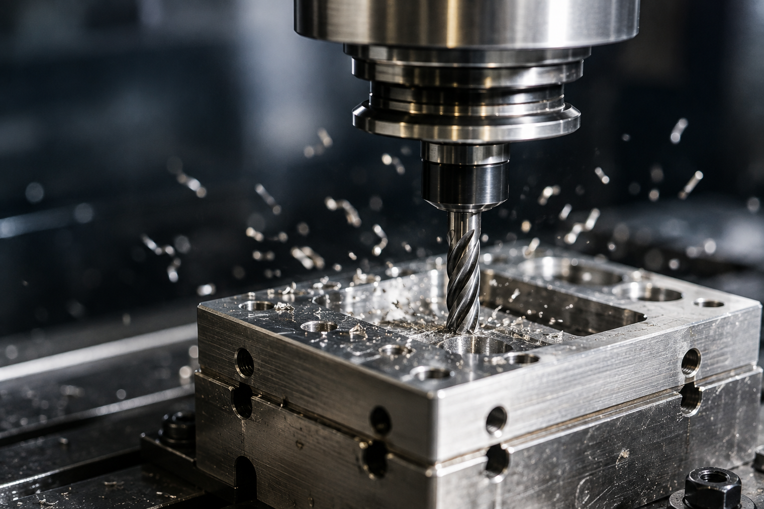
Burrs are a common result of CNC turning, milling, and drilling. They often appear around holes, edges, grooves, threads, and areas where a cutting tool exits the workpiece. Although they may seem like minor defects, uncontrolled burrs can affect assembly, dimensional accuracy, surface quality, and the final performance of a component.
Understanding how to prevent burrs in CNC machining requires more than simply removing burrs after production. Effective burr control starts with cutting tools, machining parameters, material properties, part geometry, and clearly defined quality requirements.
Burrs Can Affect Assembly, Function, and CNC Machining Quality
A machining burr is unwanted material that remains attached to the edge of a workpiece after cutting. During machining, the material does not always separate cleanly and may instead deform, stretch, or fold near the edge.
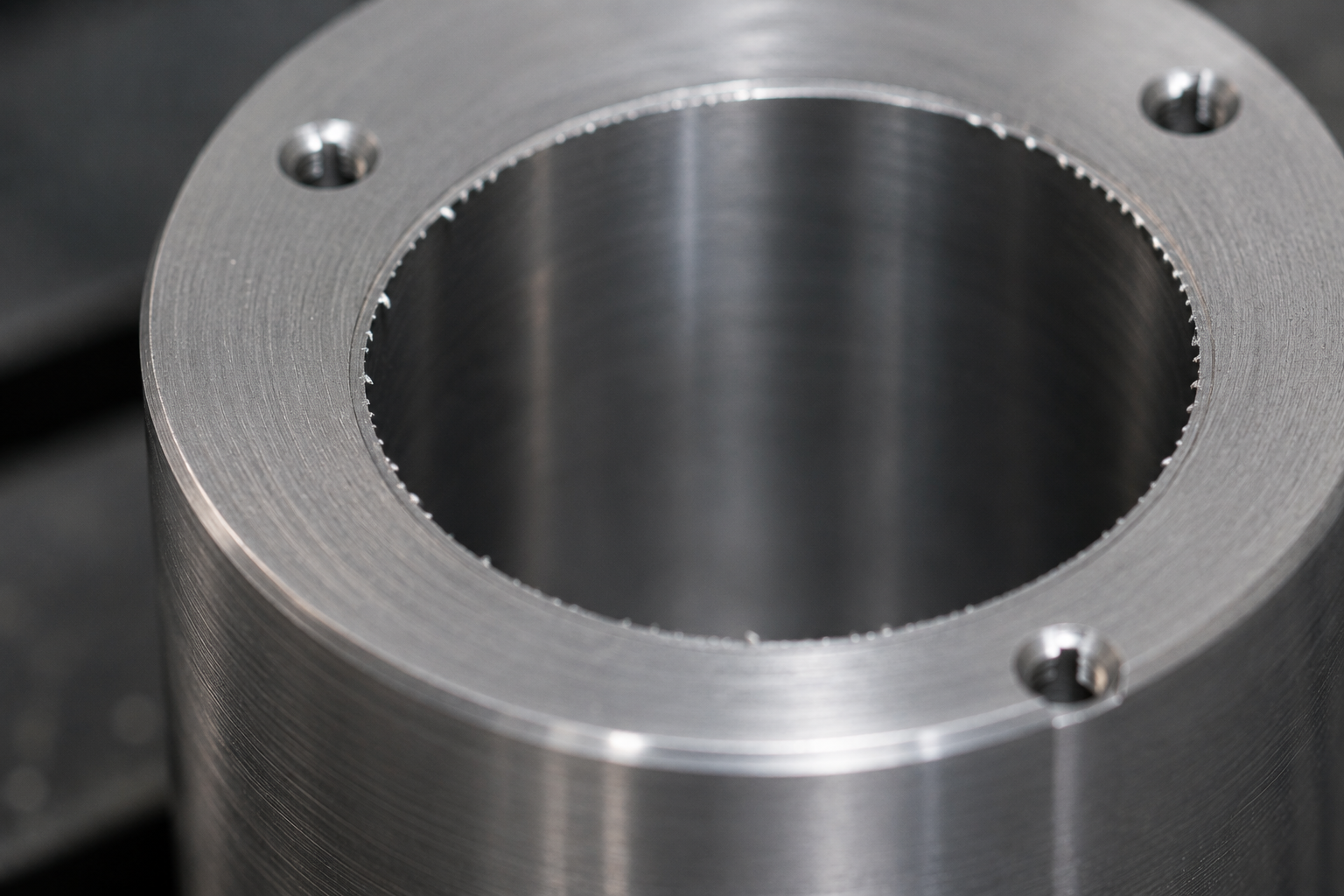
Burrs are frequently found at drilling exits, cross holes, slots, threads, thin edges, and intersecting features. Depending on their location, they can interfere with assembly, damage mating components, affect sealing performance, or create inconsistent edge conditions.
What Causes Burrs in CNC Machining?
Burr formation can be influenced by several factors, and more than one cause may occur at the same time. Identifying the root cause is important before deciding how the burr should be controlled or removed.
Cutting Tool Wear Increases Material Deformation
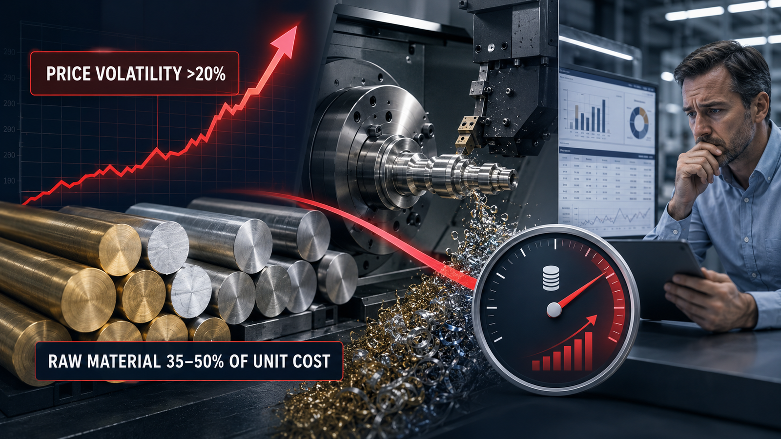
As a cutting tool becomes worn, the cutting edge becomes less effective at separating material cleanly. According to ASME machining standards, tool wear is one of the most significant contributors to inconsistent edge quality in precision machining. Instead of producing a sharp cut, the tool may push or deform the material around the edge and create a larger burr.
Tool-life management is therefore important in mass production. Replacing tools at appropriate intervals can help maintain both dimensional consistency and stable edge quality.
Cutting Parameters Directly Influence Burr Formation
Cutting speed, feed rate, depth of cut, cutting direction, and tool path can all influence the size and location of burrs. Parameters that work well for one material or geometry may not produce the same result on another component.
Optimizing machining parameters helps reduce excessive material deformation and improves the repeatability of finished edges.
Material Properties Change Burr Characteristics
Aluminum, brass, carbon steel, and stainless steel have different hardness, ductility, and machinability. More ductile materials may tend to bend or form rollover burrs, while harder materials can create different edge conditions.
Choosing suitable tooling and machining parameters according to the material is therefore an important part of burr control in precision machining.
How to Prevent Burrs in CNC Machining Before Secondary Processing
The most effective approach to how to prevent burrs in CNC machining is to reduce burr formation during cutting rather than relying entirely on secondary deburring. This can improve quality consistency and may also reduce additional processing time.
- Select cutting tools suitable for the material and geometry.
- Monitor tool wear and establish appropriate tool-change intervals.
- Optimize cutting speed, feed rate, and depth of cut.
- Adjust tool paths and machining sequences around burr-prone areas.
- Identify drilling exits, cross holes, thin walls, and intersecting features during process planning.
- Specify chamfers, radii, or edge breaks when the product design allows.
Burr-prone features should ideally be identified during drawing review. Considering these areas before mass production allows the manufacturer to establish a more stable machining and inspection process.
The Right CNC Deburring Method Depends on Part Geometry and Tolerance
Even when the machining process is optimized, some components still require additional deburring. The appropriate method depends on the material, geometry, production volume, tolerance, and accessibility of the burr.
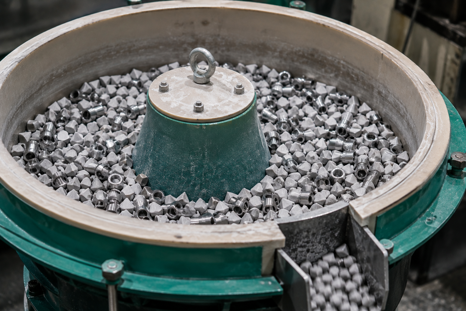
| Deburring Method | Suitable Applications | Main Considerations |
|---|---|---|
| Manual Deburring | Complex parts, prototypes, low-volume production | Flexible, but consistency depends on operator control |
| Vibratory Finishing | Small components and higher production volumes | Efficient for external edges but may alter sharp features |
| Brush Deburring | Accessible edges and hole openings | Good repeatability when the burr is accessible |
| CNC / Mechanical Deburring | Defined critical edges and repeat production | Precise but adds machining time and cost |
| Specialized Deburring | Cross holes and difficult internal features | May require dedicated equipment or external processing |
There is no single CNC deburring method that works best for every part. Excessive deburring may remove the burr successfully but can also alter a critical dimension, chamfer, radius, or edge profile.
Not Every Small Burr Should Automatically Be Considered a Defect
Burr acceptance should be based on the engineering drawing, part function, assembly requirements, and burr location rather than appearance alone. A small burr can be critical in one area but have little functional impact in another.
For example, burrs on sealing surfaces, threads, mating areas, or precision assembly features may require strict control. In contrast, a minor burr on a non-functional area that will later be overmolded or receive secondary machining may not affect the final application. This is another reason why how to prevent burrs in CNC machining should be evaluated case by case, rather than applying a single blanket standard.
Clear Drawing Requirements Reduce Burr-Related Quality Disputes
A general drawing note such as “No Burr” may appear clear, but it can still lead to different interpretations between the customer and manufacturer. Whenever possible, measurable requirements provide a more reliable acceptance standard.
- Maximum permitted burr size
- Chamfer dimensions
- Edge break requirements
- Radius requirements
- Critical and non-critical edges
- Special requirements for internal holes or cross holes
Clear specifications help suppliers choose the right machining, deburring, and inspection methods while avoiding unnecessary secondary processing.
Burr Control Should Be Built into CNC Machining Quality Control
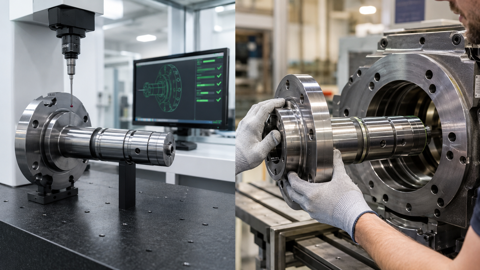
In mass production, understanding how to prevent burrs in CNC machining means treating burr control as more than a final inspection step. Drawing review, process planning, cutting-tool selection, tool-life management, in-process inspection, deburring, and final inspection all contribute to consistent edge quality.
Critical areas can be identified before production so that suitable inspection methods are established in advance. Depending on the component and customer requirements, inspection may include visual checks, dimensional verification, sampling inspection, or 100% inspection of defined characteristics.
Effective Burr Prevention Starts with Process Planning
There is no universal solution for how to prevent burrs in CNC machining. Material properties, cutting-tool condition, machining parameters, part geometry, deburring methods, and drawing requirements must all be evaluated together.
A capable CNC machining supplier should not only remove burrs after machining but also understand why they occur and establish a stable method for controlling them. Defining suitable manufacturing and acceptance criteria before mass production helps balance consistent quality, production efficiency, and cost.
Need Help with Burr, Chamfer, or Edge Requirements?
If your CNC machined components have specific requirements for burrs, chamfers, edge breaks, tolerances, internal holes, or surface treatments, our engineering team can review your drawing and evaluate a suitable manufacturing approach.